


 Reply With Quote
Its a lifestyle for sure!
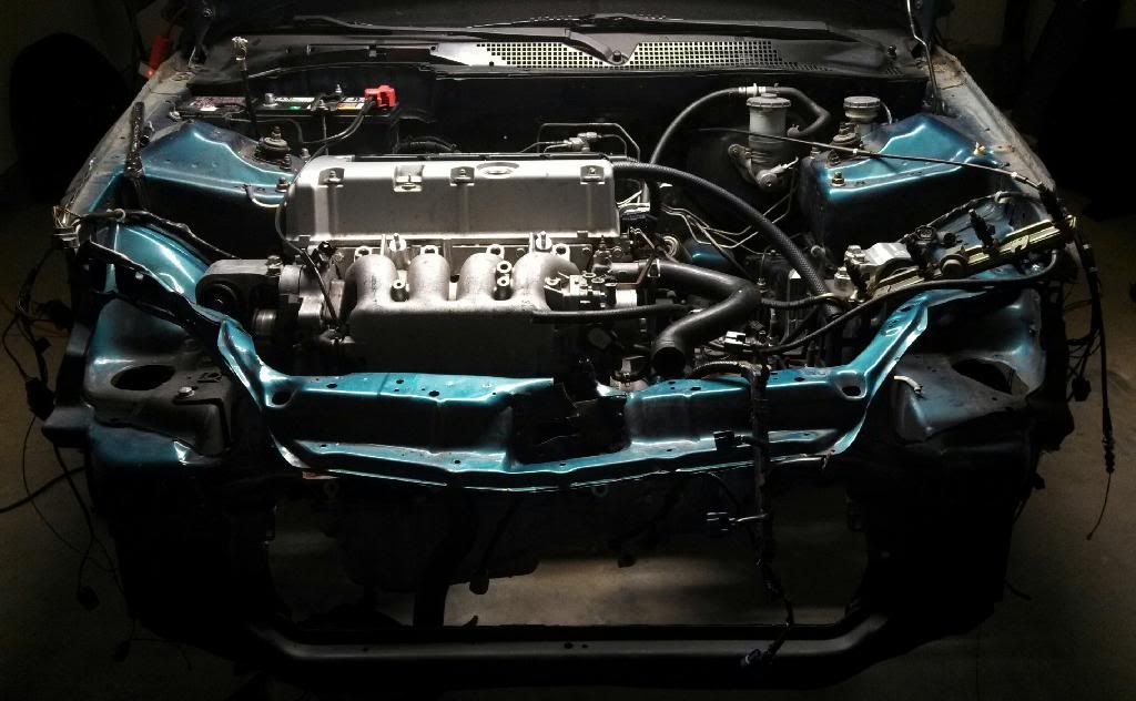
Current state...
Oh... and more to come... for real tho...


lol at the age limit. Its never too old. Wifey trying to get me out of the tuner life by 30....Originally Posted by Ba82Ep3

tits not going to happenIll build a garage in my parents big ass yard and shove a tuner in there. LMAO. take it out on weekends. =)
Cant wait for more updates Dave! I have a few questions ill shoot you a pm or email.
Bump for updates.
Sent from my SPH-L710 using Tapatalk

Its a lifestyle for sure!
Current state...
Oh... and more to come... for real tho...

Sleek
I have thought myself into a corner. I actually think i need less cam than i currently have to efficiently run this blower.
The flipped pin VTEC setup will give me a lot of air below the crossover... either in or out of boost. Since i have one valve on the VTEC lobe and the other on the secondary lobe on each side of the head for each cylinder below the crossover... im trying to shove an assload of air through the bypass out of boost. This sounds problematic... anyone care to chime in?
I can only imagine the variance of fuel ppm going into boost from part throttle... but WOT pulls from 2krpm on up should look normal, with the minimal bump at the crossover typical of flipped pin setups.

I don't know much of building k series as you know. But I was reading a Hondata article where they were saying typically when running a blower it's good to have an aggressive intake cam to let in more compressed air but use a less aggressive exhaust cam to prevent blow through.
Maybe try the setup I'll be using when I get my blower? 07 tsx intake cam k20a2 exhaust cam.

Id do more research on that cam combo you suggested. After looking at some dyno comparisons- i saw that the big tsx cam and the small rsx cam lost a good deal of power on a SC k20. My bet- its has too much intake and not enough exhaust- meaning its not getting a full fresh air charge every cycle. Id stick with what you have and focus on cooling.
Sent from my iPhone using Tapatalk
See... i was looking at the larger 06/07 TSX intake cam. Ran across a cam thread on 8th Gen and started writing down what i ran across... then compared what i could find for specs on k20a.org. The more i read... and i read for hours mind you... the more i got twisted as to what would matter this time around.
I went with my current head setup for the breathability for power on the low cam around town. Of course it would make power on the hi cam. That wasnt my goal... ive never shot for dyno queen status (not knocking those who gun for that either).
So i started thinking that my current head setup could hurt my around town drive ability... since the bypass is so damn small on the JRSC. What good is a 70mm TB and CAI gonna do when its feeding a 30mm bypass port? The 30 degrees of cam advance that works so well now wont do shit then.
So then i started thinking about cam advance... turning it down (say 20 degrees)... and how lobe duration played into that as well. But i have to consider the VTEC lobe and the secondary lobe together in this... since those two lobes hold my valves open on the low cam.
So i got frustrated and got on the Ps3 and killed some zombies... argued with the X wife... then wheeled my 1/8 RC car at the track today for some long needed practice. After focusing on other shit for a while, i think...
... this man is right. Maybe even going to both k20a2 cams considering their specs?
Or i may just go ahead and pick up either a k20a2 or k20z3 head. Prolly a k20a2... i hate the damn waterport on the k20z3 head. Wait... isnt the 06/07 TSX head the better out of all of them now? Larger ports like the k20z3 and even larger valves? Id have proper VTEC and could use the cams i have now with less worry.
Speaking of cooling... i was looking at the Skunk 2 Ultra manifold for the K series earlier. Ill never have the money to do this so im just gonna toss out the idea that hit me. Maybe someone else will do it. Use the S2 manifold base. Cast a NEW SC manifold half utilizing an m90 SC... and a much larger bypass (say 55mm). There are 8 injector bosses. Hm, i wonder what we could stuff in the extra 4 bosses? Wait... compound charging you say? A turbo feeding the SC? If only i had the coin...
Thanks for the input guys. Please feel free to kick some ideas around. Nobody on k20.org seems to wanna toss in their two cents.

http://forums.clubrsx.com/showthread.php?t=611280
Give this a read through. It has a lot of good info on cams with a SC. It also disproves a bit of what people thought was the norm for SC builds. It will explain a bit more about what i was saying about too much intake and not enough exhaust.
Sent from my iPhone using Tapatalk
Read that thread in its entirety. Thanks for the info!
So it looks like the intake cam isnt the culprit so much as the exhaust cam. Limiting VTC for intake on the low lobe/no boost considering the bypass ports size wouldnt affect the exhaust cam. But i would notice less power compared to my current NA setup on the low cam. Sounds like it kinda defeats the purpose of running the flipped pin setup. Or does it?
Bypass valve air (cruise/part throttle) would be say columns 4-7. (My setup idles at 900rpm columns 3-4, 0-5degrees cam advance, it bounces columns 3-5 sometimes and hits 10degrees advance, which i can easily change... but thats now much air there is. If i dont smooth from idle, 0-20 degrees of advance... it bucks pretty hard part throttle cruising downhill when you barely touch the gas if at all to maintain speed, jumping with the cam angle change).
I would imagine the line between bypass and boost is thin after column 7. Anyone who has datalogged with KManager can see that there is very little pedal movement needed between column 7-9/10. For NA, column 9 is most common as WOT until you hit higher RPM or have much cooler inlet temps with which it will bounce between 9 and 10. Adding boost pushes above 10... of course.
So low lobe SC bypass cruise will have less VTC advance and far less fuel (higher ignition values)... pressing to WOT low lobe will produce boost and i can increase VTC and increase fuel (decreasing ignition values). This will be fun to tune part throttle across the VTEC crossover. *sarcasm* I feel i have my work cut out for me...
Stumbled across someone mentioning the k20z1 cams were the same as the k20a ITR cams? Gonna look into this more... and compare them both to the k20z3 cams i currently have. Please add any info if found, or comment on anything ive typed!
- Dave
Im not too keen on the flip pin setups- have you basically locked the rockers so that the cam is always on the larger lobe, eliminating vtec essentially, or is something else?
I wouldnt look at other cams- i personally think you have the best oem cams for a SC 2.0L after seeing how much power the 8th gen guys are making with them. We are all just trying to keep up with them lol.
Sent from my iPhone using Tapatalk
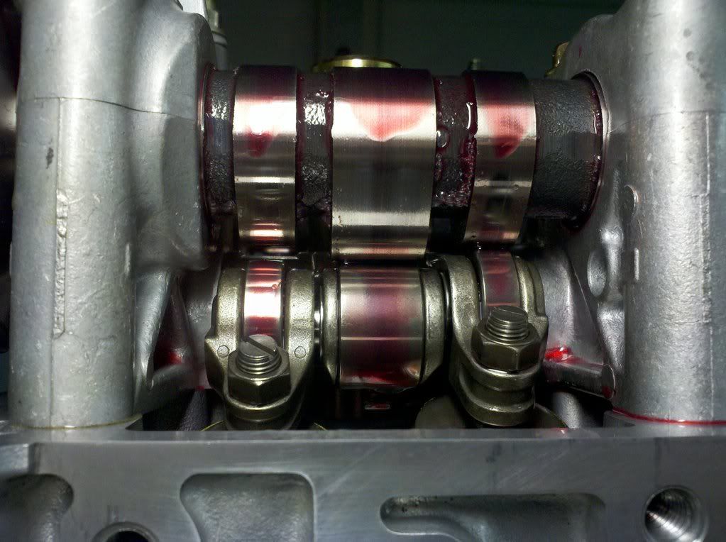
Easiest shot i have from when i was assembling the head. You can see the pin between the left rocker and the center rocker locking the left valve to the VTEC lobe below the crossover, so no lost motion assembly needed to hold a floating VTEC rocker (you can somewhat see the gap between the left rocker and its cam lobe because it is locked to the center rocker on the VTEC lobe. Its hard to tell, but the left lobe will never come in contact with its dedicated cam lobe). You can clearly see the right rocker is higher than the center/left rocker as well. The right rocker rides on its dedicated lobe on the cam until the crossover... then the pins slide at the crossover locking all three together on the big lobe. This is the same on every cylinder, both intake and exhaust.
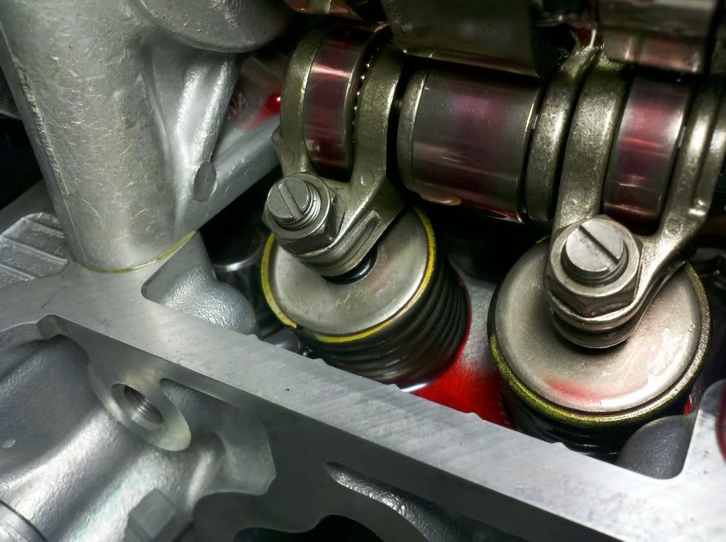
Another angle... and somewhat easier to see the gap between the left rocker and its dedicated cam lobe. The VTEC lobe is close to 25 degrees here if i remember right... you can see how far the left valve spring pair (yellow outer/red inner) is compressed compared to the right spring set on its dedicated cam lobe. That is where all the additional air comes from. In case youre curious, i used k20z3 valve lash specs. .09 and .11 if i remember right. Its been a while but it is all written down in the log book.
Im convinced after all the tune time and the dyno results that this setup makes great power (NA) below the crossover, even considering i had its nuts clipped with an OEM Accord header and OEM coupe exhaust... then opening it up with the same header with the collector hogged out to match the mandrel bent 2.5" exhaust (30whp/15wtq gain). It worked very well with the ITR trans... getting around town w/o having to crack VTEC whenever i needed power.
The problem with the setup? Three lobe rockers are SO damn heavy, steady idle (of course), and AFRs were a pain to tune (below the crossover)... likely because the air isnt flowing and stable at low RPM's so the final AFR always seems to be a bit off each time i datalogged. Add weather changes and yeah... PITA. You can see it on the dyno graph all too well.
I found both dyno sheets... ill snap pix and post them tomorrow. Been meaning to anyways.
I noticed after poking around on 8th gen the numbers they made. Started thinking i should swap to 3" exhaust to be sure i can get the spent gases out of the engine... and utilize the larger EX ports. I think it will benefit me below the crossover (in boost) as well. I still have to get the engine out of the bay and that is when i will start matching the head to the RH and know for sure how much room with the RH primaries i have to play with to match the head. That will help me decide 2.5" or 3" exhaust.
Think i should scoop up an adjustable gear for the EX cam?
randomly read your entire thread...ENJOYED...keep up the updates...
Thanks much. Its been a struggle for sure... but the joy and happiness of driving something youve put together? Its matched by few things on this planet...
Ive been on that grind to get things inline. If everything falls in place as planned it will be on the road by June. It will only be primed... but i dont care. lol I havent been able to post pix as of yet... but i will, and when i do there will be too damn many... as always. lol
subcscribed!
Been tossin around the idea of using this single fogger sniper kit. One small jet to add race fuel from a standalone tank. Maybe triggered by compressed air temp? Ideas?
I still have my OEM EP motor and fan for the radiator that mounts on the drivers side of the radiator. Id have to make an air diverter that would channel the hot air off the passenger side of the radiator to vent to the drivers side.
Still putting together the general picture of how its going to work. Will have some pixelated joy to add in a few days as well. : )
There are currently 1 users browsing this thread. (0 members and 1 guests)
 Posting Permissions


Bookmarks