

 Reply With Quote
Nice DIY...


The benefits that a traditional cold air intake has on power with K series engines have been verified over and over, yet many circuit-raced dc5's choose airboxes instead. Why?
Using a traditional cold air intake gains lots of power, but mid range can show less gains and increased lag in throttle response. This is because the filter is mounted so far from the throttle. When the throttle opens, negative pressure momentarily occurs between the filter and the throttle until air begins to flow through the filter and pressure equalizes.
Locating the filter as close as possible to the throttle would minimize this effect. To have the filter close to the throttle but still have control over air temp, an airbox design is the only option. Given that the design would be based on an airbox, the following traits would be prioritized:
-minimal throttle-filter distance
-minimal heat absorption to the box
-cold-air feed/snorkel
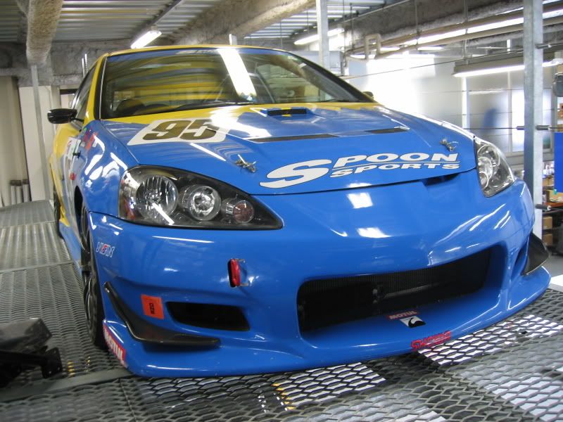
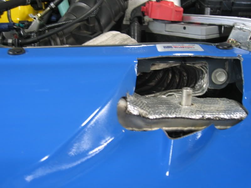
Spoon covers the factory airbox in insulation and runs a short section of dryer duct through an opening under the hood.
Here is a way to achieve a similar intake for $20:
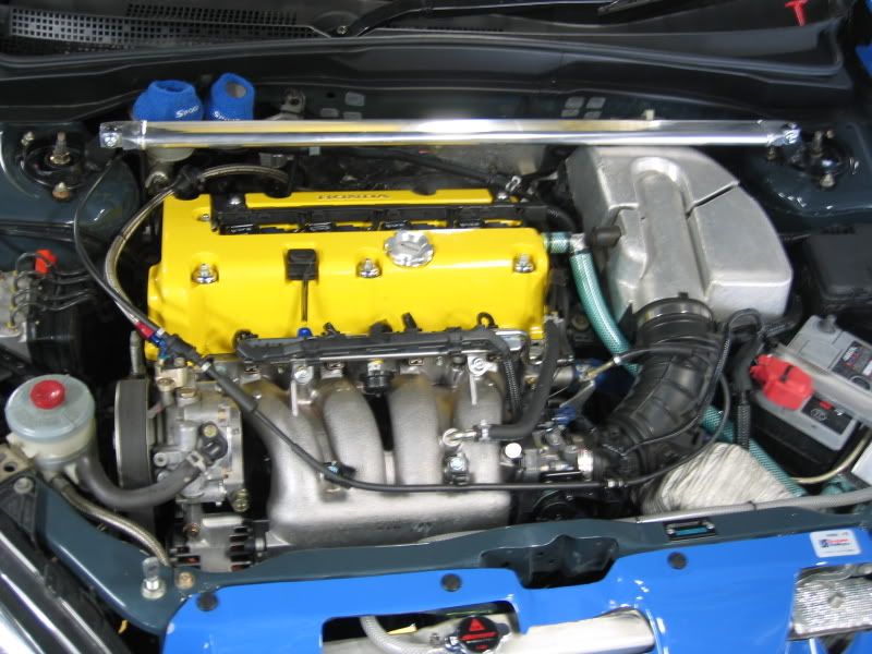
You need to relocate the battery for this to work
Parts needed:
$6 -x2 3" 90* PVC elbows
$5-17" 3" PVC tube
$10-2x Rolls of foam/foil insulation tape
-zipties
-dremel/sanding tool
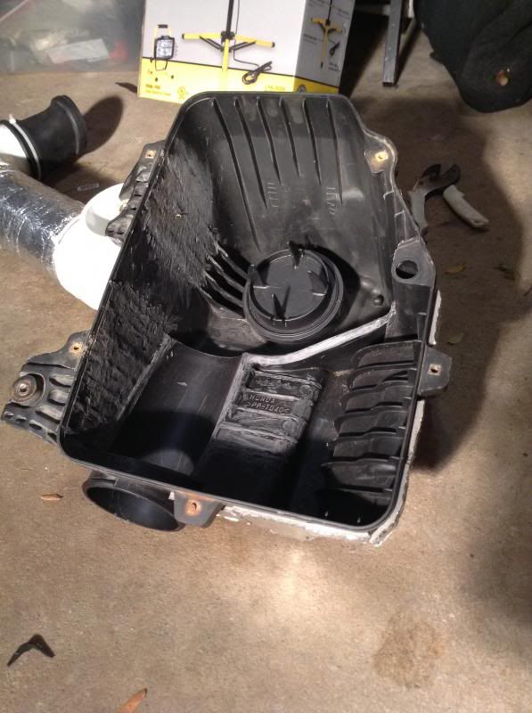
Step One:
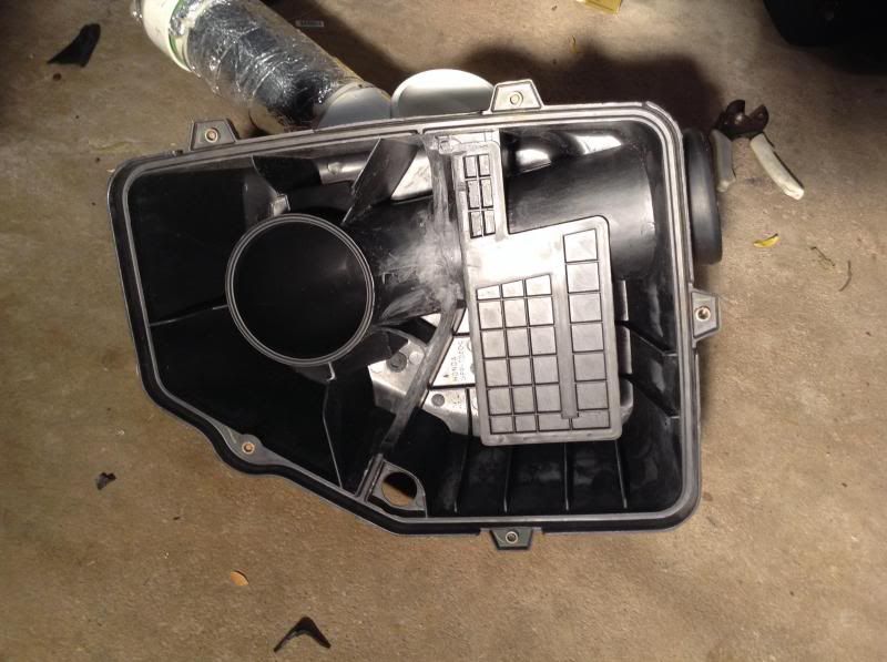
Do the hondata airbox mod
http://www.hondata.com/techkseriesairboxmod.html
The tidier you make it, the less turbulent the air, and the more the air slows down when it enters the box. Less turbulent=more power. Removing the chamber that feeds the breather would also add to this effect, and could be done by using a separate filter on the breather tube and plugging the existing hole on the airbox.
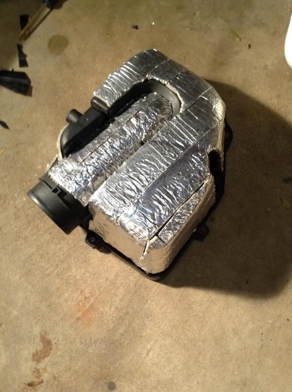
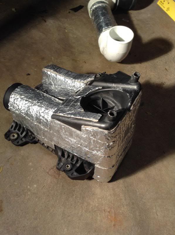
Step Two:
Cover the airbox in insulating tape. Using glue to in some places might be wise. Look for scratches on the box that were made during installation and removal. You might avoid putting tape on those spots.
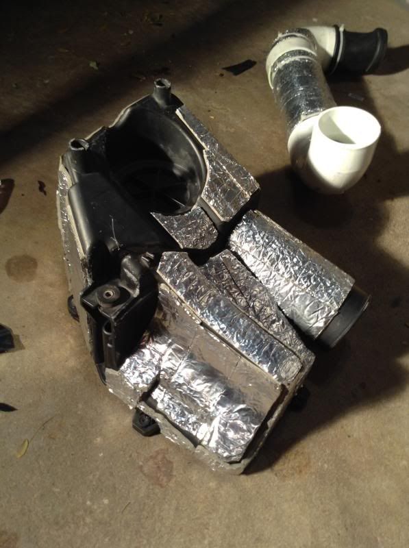
Step Three:
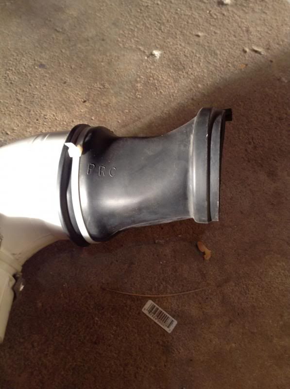
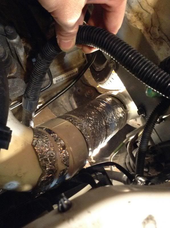
Cut the stock rubber snorkel at the last rib on the flexible section. Stretch it around the end of a 90* PVC elbow. The fit is very tight so using a sanding bit on a dremel to make a ridge around the edge of the PVC elbow will probably be necessary. Secure it with a ziptie, but first make sure it's aimed in the right direction: towards the fender~ same spot as a CAI. Attach the 3" tubing and wrap it all in insulation.
Step Four:
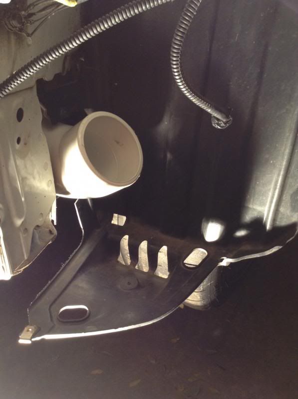
Cut an opening in the fender as if you were installing a traditional CAI. Attach the second 90* PVC elbow so that it sticks into the same spot as a CAI would.
No dyno numbers but the butt tells me it's faster for sure.

Nice DIY...

Lots of people run the duct straight to the grill, like the spoon set up. HONDATA air box mod should be similar gains wise.
Nice DIY tho. Add a K&N and call it a day.
The opening on the factory snorkel is way smaller than the opening in the 3" elbow..
The original location of the snorkel was chosen only because there is limited space. The battery is there.
Making a cold air snorkel like this would make power over stock the same way that a CAI makes power over a SRI. The reason why CAIs tend to have higher peak power than an airbox like this is because the airbox itself absorbs heat. Insulating the box like Spoon is the only solution to that.
Spoon uses the factory battery location. They might use it because their bumper has a nice opening for air, because having the battery there is better for balance, who knows... Having the battery at the factory location does, however, force you to use that spot. There's no question that the air in the bumper cavity is less turbulent than air coming in through the grill or in the engine bay... Which is more beneficial: the velocity of the air entering through the grill? Or the calmness of the air in the bumper? (temperatures would be similar because of the fender vents, view last pic)

Good job, that looks good! some guys dont' like to use the fender for air intake , they say it might suck up water.. but I had my lowered Fit with a modifed cold air in the fender and never had a problem living in the Rainiest city, Seattle. http://fitswap.org/
To suck up water with this intake the whole airbox would first need to fill with water, since the filtered air gets sucked from the top of the box. Additionally there are drainage holes at the bottom of the box. Imagine the pressure it would take to suck up the weight of the water taking up the total volume inside the PVC, plus the volume of the box. Not only do I suspect that that amount of vacuum can't occur, the system as a whole probably wouldn't seal tightly enough. It wouldn't be air tight at the PVC joints, at the drainage holes, and probably not where the top/bottom of the box join either. (with normal pressures only a minuscule amount of air would enter at any of those points)
If it is possible to hydrolock this intake, you would need to let the engine run for several seconds with the intake opening fully submerged, waiting for that entire volume to fill. By the time you got hydrolock, water would probably be coming in under the doors.
This intake has to be much safer than a CAI.

pics went missing! :O

just wondering do you have a way to monitor the intake temp?(before vs after?)
No, do you know of a way? Knowing that would be super interesting.
And are the pics still not working? They still appear for me.

Excellent stuff. This will be my next engine mod for sure.
KproOriginally Posted by bemmis

any idea if this person is using kpro ?
http://forums.clubep3.com/showthread.php?t=889394
specifically: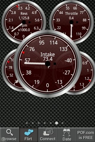
instead of using the insulation wrap, how about heat resistant paint?
http://www.por15.com/POR-20_p_52.html
any difference if the end point to different angle? upward/downward/side way/etc...
would adding a velocity stack at the end help?

What if u don't have the stock air box?
In the description:
"paint is capable of withstanding temperatures"...
"Helps prevent cracking, chipping, and peeling."
"Heat Resistant" is probably referring to its boiling point, not its insulating properties.
Air is suspended in tiny bubbles in the foam which provides insulation similarly to how air gets trapped in an animal's fur. The foil reflects heat in the same way that a space blanket does: barricading against blackbody radiation.
If you think about how the air would enter and flow about the bumper cavity the angle of the opening probably wouldn't make a difference.
Using a velocity stack crossed my mind. It couldn't hurt. The $20 cost is what made me choose not to buy it.
There are currently 1 users browsing this thread. (0 members and 1 guests)
 Posting Permissions


Bookmarks