

 Reply With Quote
Leaving this blank for the next part


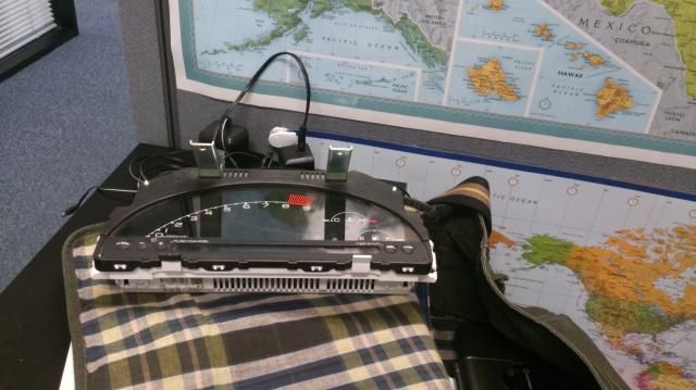
It's been a long, long while since my last DIY. This time, it will be a work-in-progress and this post will keep updated. I'll try my best to make this DIY as detailed as possible, hence will not guarantee when I'm going to update the next step.
First, for whoever is new on this. Make sure you have at least the following before you getting started:
- Any AP1 cluster or 04-05 AP2 cluster. 06+ clusters WILL NOT WORK due to Ambient Air Temperature Sensor and our EP doesn't have that function.
- S2000 cluster pigtails (not extremely necessary but will save you from trouble afterwards)
- Speedohealer v4 Universal
- Modifry ECT Module (click on THIS http://www.modifry.com/products/ect/ap2.htm)
- A piece of (whatever you can think of) as bezel. I prefer thin and relatively soft wood board.
- Big roll of 22 gauge electric wires (if you are on a budget, cut some off from junkyard would be the best for you. OEM quality too!)
- Wire cutter (get a good one, Harbor Freight has it for like $5)
- Soldering iron
- Heat shrink tubing (22 gauge or slightly bigger than OEM wire)
- Heat gun (best friend of heat shrink tubing!)
These are just some basic stuff for a complete cluster swap. You will see there are a lot more things needed as you keep on reading on this DIY.
Optional items that I have so far:
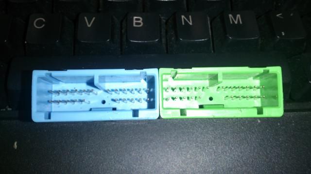
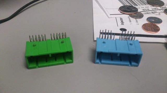
EP3 cluster female plug from broken EP3 cluster
How are you gonna remove them?
Well, just disassemble the whole cluster until only motherboard left. These 2 plugs are tied on the motherboard tight with soldering iron and plastic part of the plug is melted on the board, so you might need another person to hold the motherboard for you, then you use heat gun or desolder gun to desolder + soften the melted part. Make sure you do this in an open window area.
3M tail light repair clear red tape
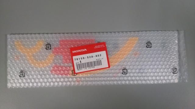
Extra diffusion plate (Part #78159-S2A-A02) for me to set a new rpm limit
_____________________________________________
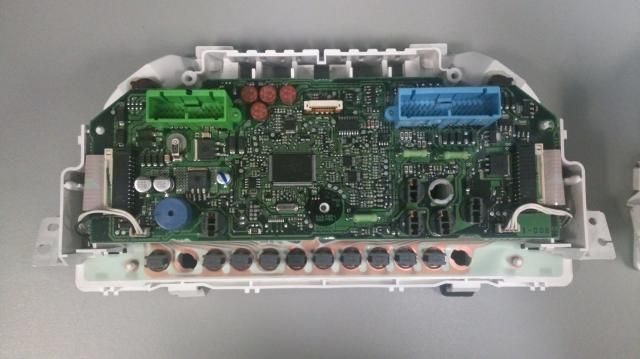
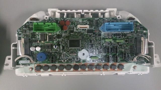
I actually have 2 S2K clusters, a 04-05 and 06+. Remember I said 06+ cluster won't work? You might ask how can you tell? Well, there are lots of ways to see the difference , but the most obvious way is to take a look at the motherboard, then you will know:
04-05 cluster
06+ cluster
When you purchase the cluster, remove screws at the back of it, take the cover off, then you should be able to see the motherboard. Use my pictures as reference so that you won't get a wrong cluster.
Oh, I got two clusters because I broke the LCD ribbon cable on 04-05 one, so I'm using 06+ LCD to replace. Make sure you learn my failure when you are trying to open the cluster! Be extremely careful on every single part. There are a few things that you aboslutely don't wanna break: LCD and motherboard, they are super expensive on Honda websites!
_____________________________________________
Part 1 (Optional): Change the redline
EP3 with K20A3 doesn't have a high redline like CTR, 6800rpm is the limit. Therefore, I should lower the redline on S2K cluster so that I won't over rev in the future. This step is not absolutely necessary if you have K swap, boosted with K-pro, or can be caucious on the red line, but I'm anal on details, so I decided to do it.
(After you open the cluster)
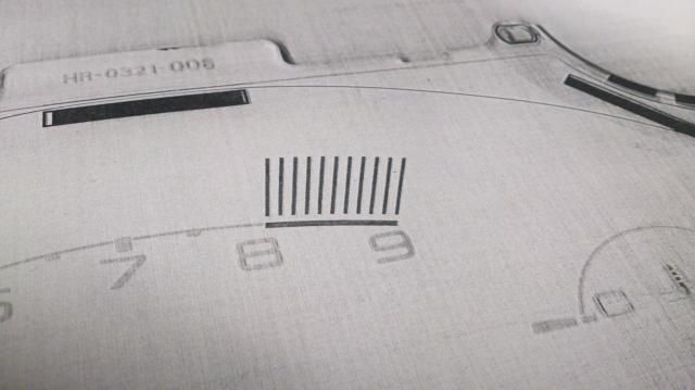
First, make photocopies of the cluster clear cover so that you can cut out this part as redline template:
One piece of template representing 1000rpm. And since I need to drop 1200 rpm, I made 2 photocopies and align them together. Use some 3M magic tape to stick the template on diffusion plate. Don't use duck tape because it's too sticky and will leave residue::
Next, align a ruler on the template, then use pencil to draw a line, then make a color photocopy of it:
Cut out the redline template, and test fit it on the diffusion plate:
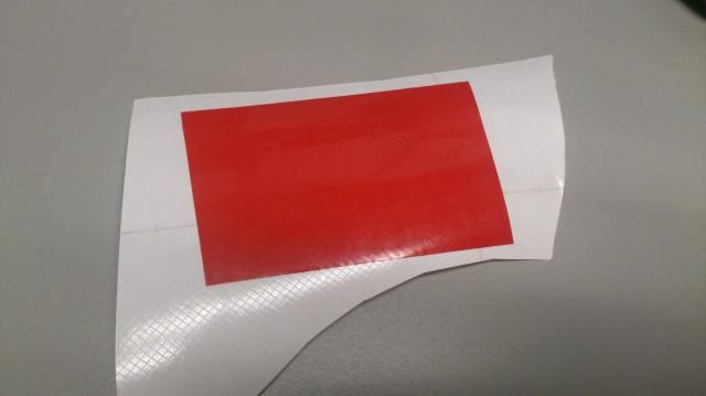
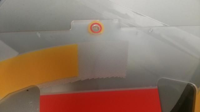
After that, cut part of the clear red tape bigger than the redline template and put it on a non sticky surface (try not to leave bubbles in between). I used leftovers from carbon fiber wrap:
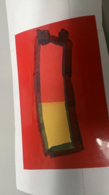
And now, I simply used my fingers to hold the template and used water marker to color between the edge of it
and red tape:
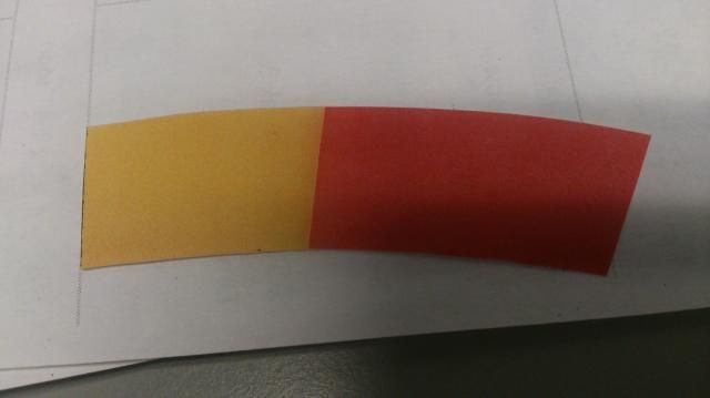
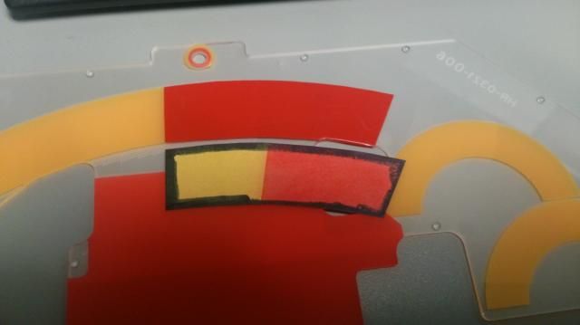
When you remove the template, you should be able to see a shape of that template. Cut it out carefully:
Test fit that cut out part on the diffusion plate:
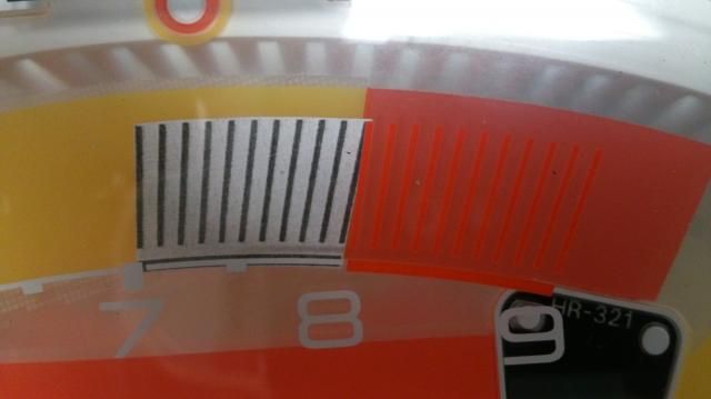
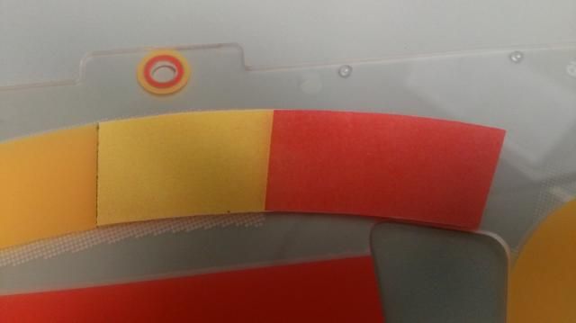
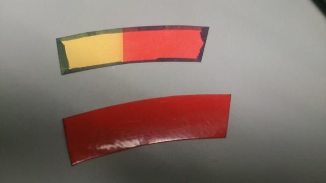
And not so fast! Now you want to put another magic tape on the left of the pencil line and align with it, then use 70% rubbing alcohol to rub off all of the colors after the line, make sure you rub carefully and not accidently rub off the rest of color parts. After you are done, peel off the magic tape, and you shall see a line like this:
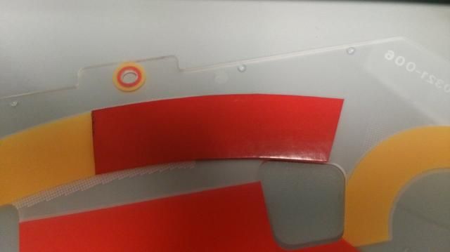
Be patience on this last step, because you want to align the clear red tape with the yellow line perfectly. It's kinda hard since you need to align and you also need to prevent bubbles. Fortunately I have screen protector installation experience so I know how to do it right.
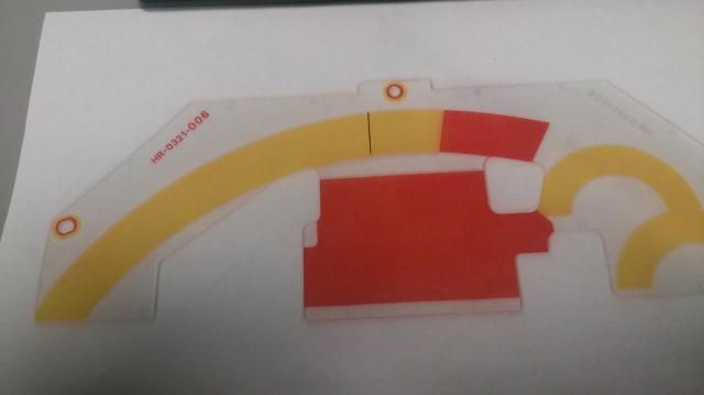
A final product...
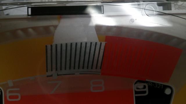
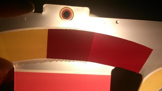
Put the diffusion plate under bright light, see if there are any bubble marks. If you find some you have to do the cut and paste again (I had to do it twice...). Here is what it should look like:
Anddddd you are done with this optional part 1!
Next step: wiring between cluster and EP3 plugs. To be continued...
Leaving this blank for the next part
Leaving this blank for the next part
Leaving this blank for the next part

Nice DIY so far...keep up the great work.
Thanks Eddie! I will get my next DIY started once I have all of the materials ready, although it might take a long time since some of them are hard to find...
Any updates on the wiring of the gauge
Sorry I only finished wirings from S2000 to EP3 plug portion. There are other wires that need to be spliced from other locations and I haven't figured out all of them just yet, plus I just lowered my car and wanna put money on finish the set up first. I'll post up whatever I have soon.Originally Posted by ramosjg


Looks cool so far, good work.
There are currently 1 users browsing this thread. (0 members and 1 guests)
 Posting Permissions


Bookmarks