

 Reply With Quote
I had an actuator kill my multiplexor, or vice-versa. it sucks!Originally Posted by Chad


im going to have to try this out

I had an actuator kill my multiplexor, or vice-versa. it sucks!

looks good... i'll probably go with red lights for mine..

I'm going to take my camera to work today and take some pics of how to wire these up. Some folks have been asking for more detail, so, I'm gonna try and remember to do this.
I should have the pics up later tonight.
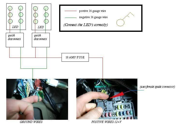
The green/red in the big harness in the kickpanel is ground. The single terminal in the picture of the fusebox at the end of my finger is used for positive. Just look at the pic. It's under and to the right of the yellow srs plug.
I used 12 LEDs to do this, roughly 8-10 feet of 16 gauge speaker wire, and the same amount of loom. A piece of plexi that was maybe...4 inches by 2 inches that I cut in half (and had to grind down alot to fit...lol). 2 fuse holders (one for the positive terminal 5 amp will do, and one for the ground pre Chad's request, put a .5 amp in there if you can.)
I dunno about 4. We just used 6 per side. I can't remember if we did 2 rows 3 or just did all 6 together....lol...it's been a couple of months since I did this.

Ok, That's cool, I recently did 4 whites in series at 12V but and they ran a bit warm AND need more voltage, it all depends on the current consumption and voltage needs of the LED as to how the voltage will drop across each, you MAY have done 6 in series because IIRC when I was pimping out my kid's quad I had like 5-6 in series at 13.8 volts and they seemed rather confortable.
I've had mixed results in series without resistors and attribute that to QC of the LED's
Chad
Ouch, and to drive the point home... how much did that cost you?

Ohh ok... I think I get it now. lol thanks
edit: so that LED part is just made out of plexi (which is like a clear plastic) with hot glue over the other side?
Correct.
I just cut some small plexi, drilled the holes in it, mounted the LEDs, soldered them up and coated the back with the glue. The glue held everything in place and keeps it from grounding out.
the multiplexor has no individual part number, so you have to purchase the underdash fuse box. honda wanted $260, but I got one used for $100. I then got the actuator for $34 after my discount.
I get it now... its not too hard. ms paint
Right?
How did you connect it to the fuse box? Is that spot always a 12 volt (hot)? What size LED is that?
btw, anyone know where to find a picture of the JDM oem ones? Post a pic for comparison. I love this thread already
Last edited by Danman281; 05-02-2008 at 01:37 PM. Reason: fix image

You could probably find some SMT (surface mount technology) LED's on Ebay or something if you look hard enough. They are small button sized LED's already mounted on a backing.

is ther any other way to wire this to your fuse box without tapping into the dome light wires? Is there an unused slot that would have been for the JDM lights but isn't used but gives the same effect or are they totally different?
When I do it in a couple weeks I plan to go to the dome light to do that so the dome light switch activates/deactivates the footlights as well. Just like in my old '78 monte carlo :D
Why the hell did the ever stop putting them in?
SMTs are PAINFULLY small to work with. It's frustrating enough to piss off the Pope.
That wire is the only one I found that works and gives the "fade" effect.
On your diagram, the wiring at the actual LED pad is incorrect, but you have the rest of it correct. I simply used a .250 female spade connector to plug into that spot on the fuse panel. That spot is constantly "hot". I forgot the size of the LEDs. I've ordered so many over the year I don't remember. I'll try and find it later tonight.
There are currently 1 users browsing this thread. (0 members and 1 guests)
 Posting Permissions


Bookmarks